Monday, November 30, 2015
YAML file configuration in Java
Reader
https://gist.githubusercontent.com/anonymous/2fa840e387829fa34a27/raw/a0e9f9d02baf5530249069f3564ca2b551b2c703/gistfile1.txt
Config
https://bitbucket.org/neenjo/tweettrends/raw/9011eb661d3b7708842f2ca1b26eb503fea79651/src/main/java/ConfigurationTwitter.java
Main
https://bitbucket.org/neenjo/tweettrends/raw/9011eb661d3b7708842f2ca1b26eb503fea79651/src/main/java/BingScreenName.java
Wednesday, November 18, 2015
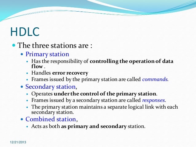
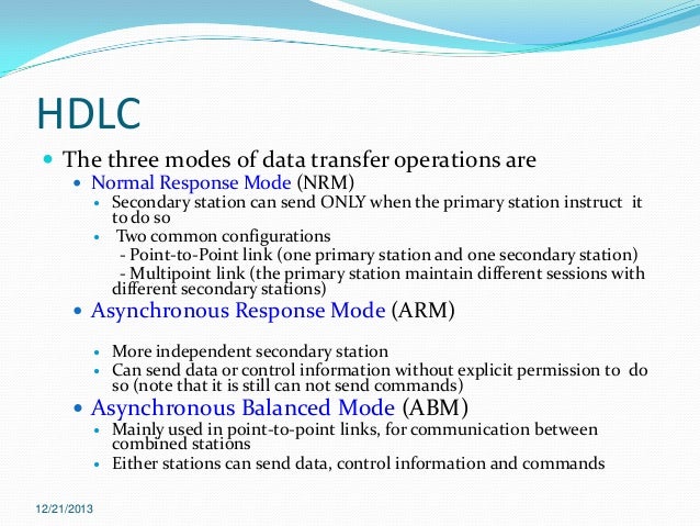
Delay Locked Loop, High-Level Data Link Control (HDLC)
DLL
Delay-Locked Loop (DLL) supports high-bandwidth data rates between devices. These DLLs are circuits that provide zero propagation delay, low-clock skew between output clock signals throughout a device, and advanced clock domain control. These dedicated DLLs can be used to implement several circuits that improve and simplify system level design.
High-Level Data Link Control (HDLC)
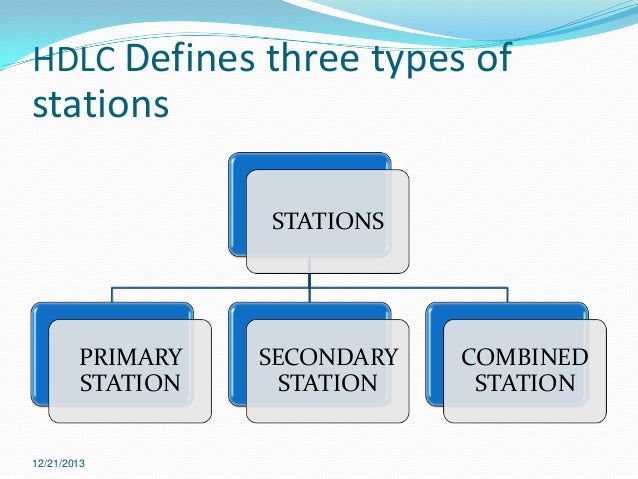
- Developed by ISO
- Support Full Duplex Communication
- p2p and multipoint data links
- Use bits [bit oriented - not byte] to set flags
OSI TCP/IP Model
Computer Networks is an interconnected collection of independent computers that are able to exchange information. The connection of these autonomous computers was firstly accomplished with copper wires, but in order to achieve greater speeds fiber optics, microwaves and communication satellites are used also.
There are five main categories of Networks:
- Local Area Networks (LANs)
- Metropolitan Area Networks (MANs)
- Wide Area Networks (WANs)
- Wireless Networks
- Internetworks
| 10m | Room | Local Area Network |
| 100m | Building | Local Area Network |
| 1Km |
Campus
| Local Area Network |
| 10Km | City | Metropolitan Area Network |
| 100Km | Country | Wide Area Network |
| 1000Km | Continent | Wide Area Network |
| 10000Km | Planet | Internet |
As far as this module is concerned LANs and Internetworks will only be discussed in detail later on of this course.
LANs are computer Networks that span a small area such as a Room, building or even a campus. There are widely used to connect workstations and personal computers. Each individual computer connected to the network has its own CPU to execute programs but is also able to access data and devices (such as printers) anywhere in the LAN. They have the advantage of transmitting information at very fast rates. Traditional LANs run at speeds 0f 10 - 100Mbit/s but the distances are limited as well as the number of computers that can be attached to a single LAN is restricted. Different kinds of topologies are possible for broadcast LANs. The most commonly used ones are shown in the figure below:

Figure 1: LAN
Topologies
- Star Topology: All devices are connected to a central hub.
- Ring Topology: All devices are connected together forming a ring. Each device is connected directly to two other devices attached to it.
- Bus Topology: The devices are connected to a central cable called the bus. Ethernet systems, discussed later on the course, use this kind of topology

Figure 2: Layers,
Protocols and Interfaces
In order to understand how the the actual communication is achieved between two remote hosts connected to the same network, a general network diagram is shown above divided into a series of layers. As it seen later on the on the course the actual number as well as their function of each layer differs from network to network. Each layer passes data and control information to the layer below It. As soon as the data are collected form the next layer, some functions are performed there and the data are upgraded and passed to the next layer. This continues until the lowest layer is reached. Actual communication occurs when the information passes layer 1 and reaches the Physical medium. This is shown with the solid lines on the diagram.
Theoretically layer n on one machine maintains a conversation with the same layer in the other machine. The way this conversation is achieved is by the protocol of each layer. Protocol is collection of rules and conventions as agreement between the communication parties on how communication is to proceed. The later is known as virtual communication and is indicated with the dotted lines on the diagram above.
As far as the above diagram is concerned another important issue to be discussed is the interface between each layer. It defines the services and operation the lower layer offers to the one above It. When a network is built decisions are made to decide how many layers to be included and what each layer should do. So each layer performs a different function and as a result the amount of information past from layer to layer is minimized.
Connection-oriented andConnectionless Services
Connection-Oriented service: The user first establishes a connection then uses the connection and then releases the connection. The sender transmits bits of information and the receiver takes them out in the same order as they were originally sent.
Connectionless: Each packet of information carries the full destination address and is routed independently from the others from the source to destination. Packets may take different routes to the destination and it is possible for two packets sent to the same destination the first one to sent can be delayed and the second one arrives first. So care must be taken in order for the all the bits arrive correctly and in the same order they were sent.
OSI Reference Model
This model employs hierarchical structure of seven layers as it is shown in figure 3 below.Click on the figure to change and rollover with the mouse for the original figure.

Figure 3: The OSI Reference Model
OSI stands for Open Systems Interconnection. It has 7-layers and attempts to abstract common features common to all approaches to data communications, and organize them into layers so that each layer only worries about the one above it and the one directly below it. Before getting into details explaining the functions and responsibilities of each layer let me clear one important statement. Although the actual data transmission is vertical, starting from the Application layer of the clients computer all the way to the Application layer of the destination computer, each layer is programmed as though the data transmission were horizontal. This can be observed by clicking on figure 3. In this figure peers are entities comprising the corresponding layers on each machine meaning that the peers that communicate using the protocol. In reality, as I stated above, no data are directly transferred from layer n on one machine to the corresponding layer on another machine.
Physical Layer
The physical layer has as a main function to transmit bits over a communication channel as well as to establish and terminate a connection to a communications medium. It is also responsible to make sure that when one side sends a '1' bit the other side will receive '1' bit and not '0' bit.Data Link Layer
Data link layer provides means to transfer data between network entities. At the source machine it takes the bit streams of data from the Network Layer breaks into frames and passes them to the physical layer. At the receiving end data link layer detects and possibly corrects the errors that may occur during the transmission and passes the correct stream to the network layer. It's also concerned with flow control techniques.Network Layer
This layer performs network routing, flow control and error control functions. Network routing simply means the way packets are routed from source to destination and flow control .prevents the possibility of congestion between packets which are present in the subnet simultaneously and formbottlenecks.Transport Layer
The Transport Layer has as a main task to accept data from the Session layer, split them up into smaller units and passes them to the Network layer making sure that all the pieces arrive correctly to the destination. It is the first end-to-end layer all he way from source machine to destination machine unlike the first three layers which are chained having their protocols between each machine. This is shown clearly in the diagram above.Session Layer
Session layer is responsible for controlling exchange information and for synchronization.Presentation Layer
It is responsible to translate different data formats from the representation used inside the computer (ASCII) to the network standard representation and back. Computers use different codes for representing character strings so a standard encoding must be used and is handled by the presentation layer. Generally in a few words this layer is concerned with the syntax and semantics of the information transmitted.Application layer
The upper layer of this model performs common application service for the application processes meaning that software programs are written in the application layer to handle the many different terminal types that exist and map the virtual terminal software onto the real terminal. It contains a variety of protocols and is concerned with file transfer as well as electronic mail, remote job entry and various other services of general interest.TCP/IP Reference Model
Figure below shows the OSI and TCP/IP network architectures illustrating the layers of the OSI model and introducing the corresponding layers on TCP/IP model.
OSI | TCP/IP |
| Application (layer 7) | Application |
Presentation (layer 6) | |
| Session (layer 5) | |
| Transport (layer 4) | Transport |
| Network (layer 3) | Internet |
| Data Link (layer 2) | Host-to-Network(Subnet) |
| Physical (layer 1) |
Figure 4: The TCP/IP Reference model.
TCP/IP reference model was named after its two main protocols: TCP (Transmission Control Protocol) and IP (Internet Protocol). This model has the ability to connect multiple networks together in a way so that data transferred from a program in one computer are delivered safely to a similar program on another computer.
Unlike the architecture of OSI model TCP/IP has 4 main layers as indicated in the table above. Before comparing the two models let as know proceed by exploring each layer in detail.
Host-to-Network Layer: It translates data and addresses information into format appropriate for an Ethernet Network or Token Ring Network. It uses a protocol (not specified due to lack of information concerned with this layer) in order for the host to connect to the network. Through this layer communication is achieved with physical links such as twisted pair or fiber optics carrying 1's and 0's.
Internet Layer: This layer is a connectionless internetwork layer and defines a connectionless protocol called IP. Its concerned with delivering packets from source to destination. These packets travel independently each taking a different route so may arrive in a different order than they were send. Internet layer does not care about the order the packets arrive at the destination as this job belongs to higher layers.
.Transport Layer: It contains two end-to-end protocols. TCP is a connection oriented protocol and is responsible for keeping track of the order in which packets are sent and reassemble arriving packets in the correct order. It also ensures that a byte stream originating on one machine to be delivered without error on any other machine on the internet. The incoming byte stream is fragmented into discrete messages and is passed to the internet layer. With an inverse process, at the destination, an output stream is produced by reassembling the received massage.
UDP is the second protocol in this layer and it stands for User Datagram Protocol. In contrast to TCP, UDP is a connectionless protocol used for applications operating on its own flow control independently from TCP. It is also an unreliable protocol and is widely used for applications where prompt delivery is more important than accurate delivery. such as transmitting speech or video.
Application Layer: Is the upper layer of the model and contains different kinds of protocols used for many applications. It includes virtual terminalTELNET for remote accessing on a distance machine, File Transfer Protocol FTP and e-mail (SMTP). It also contains protocols like HTTP for fetching pages on the www and others.
OSI versus TCP/IP
Till now we have discussed about the key features of each model and now we will talk about the differences and similarities behind the two models.Starting by stating the ways the models differ. A general statement will be that OSI Reference model was devised before protocols were invented so problems appeared with designing the model as designers didn't have much experience about the subject and did not know what functionality to put in each layer. In TCP/IP the protocols designed first and the model was built based on those protocols so they made an excellent fit. An apparent difference is that OSI has seven layers and TCP/IP has four. The later does not contain Session or Presentation layers simply because It was proven that are of little use to most applications in the OSI model. Another difference is that network layer on OSI model provides both connectionless and connection-oriented services but the corresponding layer in TCP/IP architecture, Internet layer, provides exclusively connectionless communications. TCP/IP model though, supports both modes in Transport layer but equivalent layer on OSI one model supports only connection-oriented.
Despite all these differences the two models have much in common. They are both based on the concept of a stack of independent protocols and the functionality of each layer is roughly similar.
Until this point we have talked about the two basic network architectures, OSI-RM and TCP/IP. You have maybe heart a lot more about the TCP/IP protocols rather than OSI ones but this doesn't mean that TCP/IP is the most advantageous network architecture to be of guide for designing new networks using new topologies. So further on of this course we will discuss the layers covered in the OSI model (minus Session and Presentation layers) from as they are more complete for discussing computer Networks.
Tuesday, November 17, 2015
Gigabit ethernet, Bridges, Switches, Hub, Router
Bridge
In telecommunication networks, a bridge is a product that connects a local area network (LAN) to another local area network that uses the same protocol (for example, Ethernet or token ring). You can envision a bridge as being a device that decides whether a message from you to someone else is going to the local area network in your building or to someone on the local area network in the building across the street. A bridge examines each message on a LAN, "passing" those known to be within the same LAN, and forwarding those known to be on the other interconnected LAN (or LANs).
In bridging networks, computer or node addresses have no specific relationship to location. For this reason, messages are sent out to every address on the network and accepted only by the intended destination node. Bridges learn which addresses are on which network and develop a learning table so that subsequent messages can be forwarded to the right network.
Bridging networks are generally always interconnected local area networks since broadcasting every message to all possible destinations would flood a larger network with unnecessary traffic. For this reason, router networks such as the Internet use a scheme that assigns addresses to nodes so that a message or packet can be forwarded only in one general direction rather than forwarded in all directions.
A bridge works at the data-link (physical network) level of a network, copying a data frame from one network to the next network along the communications path.
Why Bridge
Bridges are important in some networks because the networks are divided into many parts geographically remote from one another. Something is required to join these networks so that they can become part of the whole network. Take for example a divided LAN, if there is no medium to join these separate LAN parts an enterprise may be limited in its growth potential. The bridge is one of the tools to join these LANS.
Secondly a LAN (for example Ethernet) can be limited in its transmission distance. We can eliminate this problem using bridges as repeaters, so that we can connect a geographically extensive network within the building or campus using bridges. Hence geographically challenged networks can be created using Bridges.
Third, the network administrator can control the amount of traffic going through bridges sent across the expensive network media.
Fourth, the bridge is plug and play device so there is no need to configure the bridge. And suppose any machine was taken out from the network then there is no need for the network administrator to update the bridge configuration information as bridges are self configured.
Hub
A common connection point for devices in a network. Hubs are commonly used to connect segments of a LAN. A hub contains multiple ports. When a packet arrives at one port, it is copied to the other ports so that all segments of the LAN can see all packets.
Switch

In networks, a device that filters and forwards packets between LAN segments. Switches operate at the data link layer (layer 2) and sometimes the network layer (layer 3) of the OSI Reference Model and therefore support any packet protocol. LANs that use switches to join segments are called switched LANs or, in the case of Ethernet networks, switched Ethernet LANs.
Router
A device that forwards data packets along networks. A router is connected to at least two networks, commonly two LANs or WANs or a LAN and its ISP.s network. Routers are located at gateways, the places where two or more networks connect. Routers use headers and forwarding tables to determine the best path for forwarding the packets, and they use protocols such as ICMP to communicate with each other and configure the best route between any two hosts.
Routers work in a manner similar to switches and bridges in that they filter out network traffic. Rather than doing so by packet addresses, they filter by specific protocol. Routers were born out of the necessity for dividing networks logically instead of physically. An IP router can divide a network into various subnets so that only traffic destined for particular IP addresses can pass between segments. Routers recalculate the checksum, and rewrite the MAC header of every packet. The price paid for this type of intelligent forwarding and filtering is usually calculated in terms of latency, or the delay that a packet experiences inside the router. Such filtering takes more time than that exercised in a switch or bridge which only looks at the Ethernet address. In more complex networks network efficiency can be improved. An additional benefit of routers is their automatic filtering of broadcasts, but overall they are complicated to setup.
Hubs and switches
Each serves as a central connection for all of your network equipment and handles a data type known as frames. Frames carry your data. When a frame is received, it is amplified and then transmitted on to the port of the destination PC. The big difference between these two devices is in the method in which frames are being delivered.
In a hub, a frame is passed along or "broadcast" to every one of its ports. It doesn't matter that the frame is only destined for one port. The hub has no way of distinguishing which port a frame should be sent to. Passing it along to every port ensures that it will reach its intended destination. This places a lot of traffic on the network and can lead to poor network response times.
Additionally, a 10/100Mbps hub must share its bandwidth with each and every one of its ports. So when only one PC is broadcasting, it will have access to the maximum available bandwidth. If, however, multiple PCs are broadcasting, then that bandwidth will need to be divided among all of those systems, which will degrade performance.
A switch, however, keeps a record of the MAC addresses of all the devices connected to it. With this information, a switch can identify which system is sitting on which port. So when a frame is received, it knows exactly which port to send it to, without significantly increasing network response times. And, unlike a hub, a 10/100Mbps switch will allocate a full 10/100Mbps to each of its ports. So regardless of the number of PCs transmitting, users will always have access to the maximum amount of bandwidth. It's for these reasons a switch is considered to be a much better choice than a hub.
Gigabit Ethernet
Gigabit Ethernet (GbE or 1 GigE) is a term describing various technologies for transmitting Ethernet frames at a rate of a gigabit per second (1,000,000,000 bits per second), as defined by the IEEE 802.3-2008 standard. It came into use beginning in 1999, gradually supplanting Fast Ethernet in wired local networks, where it performed considerably faster. The cables and equipment are very similar to previous standards and have been very common and economical since 2010.
Gigabit Ethernet is carried primarily on optical fiber (with very short distances possible on copper media). Existing Ethernet LANs with 10 and 100 Mbps cards can feed into a Gigabit Ethernet backbone. An alternative technology that competes with Gigabit Ethernet is ATM. A newer standard, 10-Gigabit Ethernet, is also becoming available.

Physical
1000Base-SX
—Short
wavelength, multimode fiber
1000Base-LX
—Long
wavelength, Multi or single mode fiber
1000Base-CX
—Copper
jumpers <25m, shielded twisted pair
1000Base-T
—4
pairs, cat 5 UTP
—
Signaling
- 8B/10B
Datalink Layer, Framing, MAC, ALOHA, CSMA, 802.3, 802.5
Introduction.
This layer has as a primary responsibility to provide error-free transmission of data information between two remote hosts (computers) attached to the same physical cable. At the source machine it receives the data from the Networks Layer, groups them into frames and from there are sent to the destination machine. From that point the data are received from the Data Layer at the destination, a checksum is computed there to make sure that the frames sent are identical with those received and eventually the data are passed to the Network Layer.Although the actual transmission is end-to-end, it is easier to think in terms of the two Data Link Layers processing communication using a data link protocol via a virtual data path.. The actual data path follows the route depicted in the previous tutorials (Source machine: Network Layer - Data Link Layer - Physical Layer - cable --> Destination: cable - Physical Layer - Data Link Layer - Network Layer) as shown in figure below.

There are three basic services that Data Link Layer commonly provides:
- Unacknowledged connectionless service.
- Acknowledged connectionless service.
- Acknowledged connection oriented service
The second case is a more reliable service in which every single frame, as soon as it arrives to destination machine is individually acknowledged. In this way the sender knows whether or not the frame arrived safely to the destination. Acknowledged connectionless service is useful in unreliable channels such as wireless systems.
Finally we have acknowledged connection oriented service. The source and destination machines establish a connection before any data are transferred. Each frame sent is number, as if it has a specific "ID", and the data link layer guarantees that each frame sent is indeed received by the other end exactly once and in the right order. This service is said to be the most sophisticated service the data link layer can provide to Network layer.
Framing
Framing is a technique performed by the Data Link layer. In the source machine Data link layer receives a bit stream of data from the network layer. It breaks the bit stream into discrete frames and computes a checksum, Then the frame is sent to the destination machine where the checksum is recomputed. In case were it is different from the one contained in the frame an error has occurred and data link layer discards it and sends an error report.There are many methods of breaking a bit stream into frames but I will like to concentrate in only two of them. This procedure might appear easy but instead is a very delicate method as there is difficulty by the receiving end to distinguish among the frames that were sent.
The first method is called character stuffing. There is a specific sequence of characters representing the start and the end of each frame. Start is represented with DLE STX and the end with DLE ETX. (DLE stands for dada link escape, STX start of text and ETX end of text). So in case the destination loses track of the frame boundaries, it looks for the this sequence of characters to figure out where it is. The problem with this approach is that these bit pattern might occur within the data sequence. In order to overcome this problem the sender's data link layer inserts an ASCII DLE character just before each "accidental" DLE character in the data. In the receiving machine, data link layer removes this stuffed character and passes the original data to the network layer. The technique is shown graphically in the figure below.

- The first sequence shows the original data sent by the network layer to data link layer. Case (b) shows the data after being stuffed and case (c) are the data passed to the network layer on the receiving machine.
Another technique used for framing is called bit stuffing. It is analogous to character stuffing but instead of ASCII characters it adds bits to a bit stream of data. The beginning and end of a frame contains a special pattern of 01111110 called a flag byte. Therefore, if the actual data being transmitted has six 1's in a row, a zero is inserted after the first 5 1's so that the data is not interpreted as a frame delimiter. On the receiving end, the stuffed bits are discarded, in the same way as in character stuffing technique explained before, and passed to the network layer. A demonstration of this technique can be shown in the diagram below below:

(a) Is the original bit stream
(b) Shows the data after being stuffed in the source's machine data link layer. Whenever it counters five consecutive ones in the data, it automatically stuffs a 0 bit into the stream.
(c) The after destuffing by the receiver's data link layer.
There are mainly two conditions of transmitting data frames handled by protocols in this layer. The first one is data frames are sent in only one direction. Meaning that only one machine wishes to transmit data to another machine as shown below.

Sender transmits data frame data1. The receiving machine receives the frame and sends an acknowledgement. As soon as the acknowledgement goes back to the sender another data frame is transmitted, data2. For some reasons data2 does not arrive at the destination so the receiver does not send an acknowledgement as it has never received the frame. Sender waits for certain time to receive the acknowledgement. Time out occurs as the acknowledgement did not arrive and sender retransmits the same data frame. This time the data arrive correctly and an acknowledgement of data2 is sent by the receiver.
There are cases though, that there is need for data to be sent in both directions simultaneously. One way to achieve this is by having two separate communication channels, one for data and one for acknowledgements. In this case the reverse channel for acknowledgements is completely wasted as we have two circuits and we use the capacity of one. A better idea is to use the same circuit for data in both directions. So by intermixing data frames from A and B with the acknowledgement frame from A to B and placing a header to each frame we can distinguish the data frame from the acknowledged one. When a data frame arrives, instead of immediately sending a separate control frame, the receiver restrains itself and waits until the network layer passes it the next packet. The acknowledgment is attached to the outgoing data frame. In effect, the acknowledgment gets a free ride on the next outgoing data frame. This technique is widely known as piggybacking.
HDLC
An example of what we have seen so far is the HDLC (High-level Data Link Protocol) commonly known as X.25. It is a widely used data link protocol, that is bit oriented and uses bit stuffing, like all the other protocols originated in this layer. All bit oriented protocols use a common frame structure shown in the following figure.
You can recognize the frame boarders as they consists of the same bit pattern of 01111110 (flag byte) to indicate the start and the end of the frame. It contains anaddress field used to identify one of the terminals on multi-drop lines. The control field used for sequence numbers, acknowledgement and other purposes. The datafield that contain arbitrary information and the Check-Sum field.
The Medium Access Sublayer (MAC)
This section deals with broadcast networks and their protocols. The basic idea behind broadcast networks is how to determine who gets to use the channel when many users want to transmit over it. The protocols used to determine who goes next on a multiaccess channel belong to a sublayer of the data link layer called MAC.Pure ALOHA
One of the newly discovered algorithms-protocols for allocating a multiple access channel is ALOHA. The idea is simple. Users transmit whenever they have data to be sent. Frames are destroyed when collision occurs. When a sender detects a collision waits for a random amount of time and retransmits the frame. With this method the best theoretical throughput and channel utilization we can have is 18%. Term throughput means the amount of work that a computer can do in a given time periodSlotted ALOHA
In slotted ALOHA time is divided into discrete intervals, each corresponding to one frame. A computer is not permitted to send whenever it has data to send. Instead it is required to wait for the next available slot. The best it can be achieved is 37% of slots empty, 37% success and 26% collision.Nonpersistent CSMA (Carrier Sense Multiple Access)
Before sending, a station senses the channel. If no one else is sending, the station begins doing so itself. However, if the channel is already in use, waits a random time and then repeats the algorithm.1-Persistent CSMA/CD (Carrier Sense Multiple Access with Collision Detection)
Is an improvement of the previous techniques When a station wants to transmit listens to the cable (carrier sense). If its busy waits until it goes idle, otherwise it transmits. If two or more stations simultaneously begin transmitting on an idle cable they will collide. As soon as they detect a collision stations abort their transmission (collision detection). This is very important enhancement as it saves time and bandwidth. Then stations wait a random time and repeat the whole process al over again. CSMA/CD is widely used on LANs in MAC sublayer such as Ethernet, Token Ring, Token bus etc.

IEEE Standard 802.3 and Ethernet
Ethernet is the most widely-installed Local Area Network technology. Is specified in a standard called IEEE 802.3 (Institute of Electrical and Electric Engineers). An Ethernet LAN typically uses coaxial cable or twisted pair wires. It provides speeds up to 10 Mbps. The devices connected to the LAN compete for access using CSMA/CD protocol. The figure below is an animated gif explaining the basic operation of an Ethernet. Click on the image to restart it.
Machine 2 wants to send a message to machine 4, but first it 'listens' to the cable to make sure that no one else is using the network.
If it is all clear it starts to transmit its data on to the network (represented by the yellow flashing screens). Each packet of data contains the destination address, the senders address and the data to be transmitted.
The signal moves down the cable and is received by every machine on the network but because it is only addressed to number 4, the other machines
ignore it.
Machine 4 then sends a message back to number 1 acknowledging receipt of the data (represented by the purple flashing screens).
As I stated before, there is a possibility of two machines try to transmit simultaneously over the cable. The result can be observed in the following animated figure.

What happens is that machine 2 and 5 decide to transmit at the same time.
The packets collide and each machine has the ability to detect the collision and immediately abort transmission.
Then they wait for random period of time and transmit again.
IEEE Standard 802.5: Token Ring
The token ring protocol is the second most widely-used protocol on local area networks after Ethernet. The IEEE 802.5 token ring technology provides for data transfer rates of either 4 or 16 Mbps. It is a collection of individual point-to-point links, connecting each terminal, that happen to form a circle. The token ring operation could be seen with the help of the animated figure below.How it works: A special 3 byte bit pattern called a "token" circulates around the ring. A station wishing the transmit on the ring must seize the token. The station then alters one bit of the token which then becomes the first part of the normal data frame the station wishes to transmit. Only having one token on the ring means that only one station can transmit at a time. This solves the problem of contention and access to the common media.
| In the example, machine 1 wants to send some data to machine 4. It captures the token, writes its data and the recipient's address onto the Token (indicated by the yellow flashing screen). The packet of data travels first to machines 2 and 3 that read the address, realize it is not its own, and pass the token to machine 4. This time it is the correct address and so number 4 stores the packet (represented by the yellow flashing screen). Then machine 4 sends an acknowledgement back to machine 1 to say that it has received the packet (represented by the purple flashing screen). Machine 5 and 6 forward the acknowledgement to machine 1, who sent the original message. As soon as Machine 1 receives the acknowledgement, from machine 4 (indicated by the purple flashing screen) regenerates the free Token back on to the ring ready for the next machine to use. |  |
Mac Sublayer
In the IEEE 802 reference model of computer networking, the medium access control or media access control (MAC) layer is the lower sublayer of the data link layer (layer 2) of the seven-layer OSI model. The MAC sublayer provides addressing and channel access control mechanisms that make it possible for several terminals or network nodes to communicate within a multiple access network that incorporates a shared medium, e.g. an Ethernet network. The hardware that implements the MAC is referred to as a media access controller.
The MAC sublayer acts as an interface between the logical link control (LLC) sublayer and the network's physical layer. The MAC layer emulates a full-duplex logical communication channel in a multi-point network. This channel may provide unicast, multicast or broadcast communication service
http://www.ee.surrey.ac.uk/Projects/CAL/networks/Data-Link_Layer.htm
Primary Function Of MAC
- Addressing of destination stations (both as individual stations and as groups of stations)
- Conveyance of source-station addressing information
- Transparent data transfer of LLC PDUs, or of equivalent information in the Ethernet sublayer
- Protection against errors, generally by means of generating and checking frame check sequence
- Control of access to the physical transmission medium
- Frame delimiting and recognition
Saturday, November 14, 2015
MIME (Multi-Purpose Internet Mail Extensions)
MIME (Multi-Purpose Internet Mail Extensions) is an extension of the original Internet e-mail protocol that lets people use the protocol to exchange different kinds of data files on the Internet: audio, video, images, application programs, and other kinds, as well as the ASCII text handled in the original protocol, the Simple Mail Transport Protocol (SMTP). In 1991, Nathan Borenstein of Bellcore proposed to the IETF that SMTP be extended so that Internet (but mainly Web) clients and servers could recognize and handle other kinds of data than ASCII text. As a result, new file types were added to "mail" as a supported Internet Protocol file type.
Servers insert the MIME header at the beginning of any Web transmission. Clients use this header to select an appropriate "player" application for the type of data the header indicates. Some of these players are built into the Web client or browser (for example, all browsers come with GIF and JPEG image players as well as the ability to handle HTML files); other players may need to be downloaded.
New MIME data types are registered with the Internet Assigned Numbers Authority (IANA).
MIME is specified in detail in Internet Request for Comments 1521 and 1522, which amend the original mail protocol specification, RFC 821 (the Simple Mail Transport Protocol) and the ASCII messaging header, RFC 822.
http://www.tutorialspoint.com/html/mime_media_types.htm
Friday, November 13, 2015
H.323 , SIP Standards, Gatekeeper
H.323
H.323 is a standard approved by the International Telecommunication Union (ITU) in 1996 to promote compatibility in videoconference transmissions over IP networks. H.323 was originally promoted as a way to provide consistency in audio, video and data packet transmissions in the event that a local area network (LAN) did not provide guaranteed service quality (QoS). Although it was doubtful at first whether manufacturers would adopt H.323, it is now considered to be the standard for interoperability in audio, video and data transmissions as well as Internet phone and voice-over-IP (VoIP) because it addresses call control and management for both point-to-point and multipoint conferences as well as gateway administration of media traffic, bandwidth and user participation.H.323, which describes how multimedia communications occur between terminals, network equipment and services, is part of a larger group of ITU recommendations for multi-media interoperability called H.3x. The latest of these recommendations, H.248, is a recommendation to provide a single standard for the control of gateway devices in multi-media packet transmissions to allow calls to connect from a LAN to a Public Switched Telephone Network (PSTN), as well as to other standards-based terminals. This recommendation was announced in August 2000, by the ITU-TU Study Group 16 and the Megaco Working Group of the Internet Engineering Task Force (IETF).
Gatekeeper
A gatekeeper is a management tool for H.323 multimedia networks. A single gatekeeper controls interactions for each zone, which comprises the terminals, multipoint control units (MCUs), and gateways within a particular domain. Although the gatekeeper is an optional component, when it is included, it becomes the central administrative entity.
Depending on the demands of the specific network, the gatekeeper oversees authentication, authorization, telephone directory and PBX (private branch exchange) services, as well as call control and routing. Other functions may include monitoring the network for load balancing and real-time network management applications, intrusion detection and prevention, and providing interfaces to legacy systems. Gatekeepers are available as either hardware devices or software applications, and are offered as proprietary products from a number of vendors, including Cisco and Symantec, or as freeware.
SIP
SIP (Session Initiation Protocol) is a signaling protocol used to create, manage and terminate sessions in an IP based network. A session could be a simple two-way telephone call or it could be a collaborative multi-media conference session. This makes possible to implement services like voice-enriched e-commerce, web page click-to-dial or Instant Messaging with buddy lists in an IP based environment.
SIP has been the choice for services related to Voice over IP (VoIP) in the recent past. It is a standard (RFC 3261) put forward by Internet Engineering Task Force (IETF). SIP is still growing and being modified to take into account all relevant features as the technology expands and evolves. But it should be noted that the job of SIP is limited to only the setup and control of sessions. The details of the data exchange within a session e.g. the encoding or codec related to an audio/video media is not controlled by SIP and is taken care of by other protocols.
VoIP
VoIP (Voice over Internet Protocol) is a great technology that allows you to make and receive telephone calls over the Internet. It can also be referred to as an Internet Phone. VoIP(Voice over IP) enables you to make cheap telephone calls over a broadband Internet connection, (usually a DSL, broadband cable connection, or T1), instead of using your regular telephone service
First, voice is converted by an ATA (Analog Telephone Adapter) or IP phone, from an analog signal to a digital signal. It is then sent over the Internet in data packets to a location that will be close to the destination. Then it will be converted back to an analog signal for the remaining distance over a traditional circuit switch (PSTN) (unless it is VoIP to VoIP). Your call can be received by traditional telephones worldwide, as well as other VoIP users. VoIP to VoIP calls can travel entirely over the Internet. Since your voice is changed to digital (so that it can travel over the Internet), other great features such as voice messages to email, call forwarding, logs of incoming and outgoing calls, caller ID, etc., can be included in your basic calling plan all for one low price. Many of these special features are great for the small business person who relies on their phone service to be more a information center rather than just a telephone.
Uses PCM
Introduction to the World Wide Web
The "Web", short for "World Wide Web" (which gives us the acronym www), is the name for one of the ways that the Internet lets people browse documents connected by hypertext links.
The concept of the Web was perfected at CERN in 1991 by a group of researchers which included Tim-Berners Lee, the creator of the hyperlink, who is today considered the father of the Web.
The principle of the Web is based on using hyperlinks to navigate between documents (called "web pages") with a program called a browser. A web page is a simple text file written in a markup language (called HTML) that encodes the layout of the document, graphical elements, and links to other documents, all with the help of tags.
Besides the links which connect formatted documents to one another, the web uses the HTTP protocol to link documents hosted on distant computers (called web servers, as opposed to the client represented by the browser). On the Internet, documents are identified with a unique address, called a URL, which can be used to locate any resource on the Internet, no matter which server may be hosting it.
Thursday, November 12, 2015
Using pipe() command in Linux
 #include<unistd.h>
 #include<stdio.h>
 main()
 {
 int pid;        //storing process id in case of fork
 char str[15];      //array used to input string in parent
 char str2[15];     //array for receiving string in child
 int pipeArray[2];    //pipe file descripter 'pipeArray[0] = end of pipe used to read' and 'pipeArray[1] = end of pipe used to write'
 if(pipe(pipeArray)==-1) //error in creating pipe
     {
     printf("\nError\n");
     exit(0);
     }
 pid=fork();       //forking initiating parent and child
 if(pid==-1)       //error in fork
     printf("\nError\n");
 else if(pid==0)     //pid=0 means child
     {
     //child
     close(pipeArray[1]);      //close write file descripter as we will only be reading
     read(pipeArray[0],str2,15);   //read from file descripter, use 'man 2 read' command in linux to understand it
     close(pipeArray[0]);      //closing read pipe after use
     printf("\nI am the famous Child -%s",str2);   }
 else
     {
     //parent
     close(pipeArray[0]);      //close read fd
     printf("\nenter String\n");
     scanf("%s",str);
     write(pipeArray[1],str,15);   //write to file descriptr
     close(pipeArray[1]);      //close write pipe after use
     wait();             //wait for child process to complete
     }
 }
Wednesday, November 11, 2015
Socket Programming Basics Part 2
Part 1: http://programmingundersecurity.blogspot.in/2014/01/understanding-socket-programming-part-1.html
Header Files Used
#include <netinet/in.h> - Constants and strucutres needed for Internet Domain Address #include <sys/socket.h> -Structures needed for sockets #include <sys/types.h> - Data types used in System callsClient Side Procedures
- Create a socket with socket() system call
- Connect the socket to the address of the server using the connect() system call.
- Send and receive data. There are a number of ways to do this, but the simplest way is to use the read() and write() system calls.
- Create a socket with the socket() system call.
- Bind the socket to an address using the bind() system call. For a server socket on the Internet, an address consists of a port number on the host machine.
- Listen for connections with the listen() system call.
- Accept a connection with the accept() system call. This call typically blocks the connection until a client connects with the server.
- Send and receive data using the read() and write() system calls.
Structures Used
Understand about various structures from herehttp://www.tutorialspoint.com/unix_sockets/socket_structures.htm
Server Code : http://www.cs.rpi.edu/~moorthy/Courses/os98/Pgms/server.c
Client Code: http://www.cs.rpi.edu/~moorthy/Courses/os98/Pgms/client.c
Other Tutorial: https://www.cs.cf.ac.uk/Dave/C/node28.html
Saturday, November 7, 2015
Neuroph - Java Neural Network Framework
Download Link
http://neuroph.sourceforge.net/download.html
Basic Tutorial using AND
http://neuroph.sourceforge.net/Getting%20Started%20with%20Neuroph%202.7.pdf
Dataset Source
http://neuroph.sourceforge.net/image_recognition.html
Source Of Tutorial
http://neuroph.sourceforge.net/image_recognition.html


Select Neuroph Project, and click Next.

Enter project name and location, click Finish.


Select Image Recognition file type, and click Next.


http://neuroph.sourceforge.net/download.html
Basic Tutorial using AND
http://neuroph.sourceforge.net/Getting%20Started%20with%20Neuroph%202.7.pdf
Dataset Source
http://neuroph.sourceforge.net/image_recognition.html
Source Of Tutorial
http://neuroph.sourceforge.net/image_recognition.html
IMAGE RECOGNITION WITH NEURAL NETWORKS
Neural networks are one technique which can be used for image recognition. This tutorial will show you how to use multi layer perceptron neural network for image recognition. The Neuroph has built in support for image recognition, and specialised wizard for training image recognition neural networks. Simple image recognition library can be found in org.neuroph.contrib.imgrec package, while image recognitionwizard in Neuroph Studio canis located in [Main Menu > File > New > Image recognition neural network]
This tutorial will explain the following:
1. Basic principle how multi layer perceptrons are used for image recognition (one possible approach is described here)
2. How to train neural networks for image recognition with Neuroph Studio
3. How to use neural networks trained for image recognition in your applications
2. How to train neural networks for image recognition with Neuroph Studio
3. How to use neural networks trained for image recognition in your applications
This tutorial is for Neuroph v2.6.
1. Image Recognition with Multi Layer Perceptron
Every image can be represented as two-dimensional array, where every element of that array contains color information for one pixel. (picture 1)
Picture 1. Image colors
Each color can be represented as a combination of three basic color components: red, green and blue.
Picture 2. RGB color system
So, to represent some image in a RGB system we can use three two-dimensional arrays, one for each color component, where every element corresponds to one image pixel.
int [][] redValues
int [][] greenValues
int [][] blueValues
int [][] greenValues
int [][] blueValues
For example, if pixel at location [20, 10] has color RGB[33, 66, 181] we have
redValues[10][20] = 33;
greenValues[10][20] = 66;
blueValues[10][20] = 181;
greenValues[10][20] = 66;
blueValues[10][20] = 181;
The dimensions of each of these arrays are [imageHeight][imageWidth]
We can merge these three arrays into a single one-dimensional array so it contains all red values, then all green and at the end all blue values. Thats how we create flattenedRgbValues[] array.
The dimension of this array is [imageHeight * imageWidth * 3]
Now we can use this one-dimensional array as input for neural network, and to train neural network to recognize or classify them. Multi layer perceptrons are type of neural networks suitable for this tasks (picture 3).
The dimension of this array is [imageHeight * imageWidth * 3]
Now we can use this one-dimensional array as input for neural network, and to train neural network to recognize or classify them. Multi layer perceptrons are type of neural networks suitable for this tasks (picture 3).
Picture 3. Feeding multi layer perceptron with color information from image. Each input neuron corresponds to one color component (RGB) of one image pixel at a specific location.
Each output neuron corresponds to one image or image class. So if network output is [1, 0, 0] that means that input is recognized as 'image A'.
We can create training set for training neural network as set of pairs of input (flatten rgb arrays), and output vectors (where corresponding image neuron is 1).
Network can be trained by using Backpropagation learning algorithm. In next section we'll provide some details about the neural netwok and learnig algorithm.
2. Training Neural Network for Image Recognition with Neuroph Studio
Neuroph Studio provides environment for creating and training neural networks, which can be saved as ready-to-use java components. Also it provides specialised image recognition tool to train neural networks for image recognition. Creating and training neural network for image recognition consists of the following steps:
- Create Neuroph project
- Create image recognition neural network
- Train network
- Test network
- Save & deploy network
Step 1. To create Neuroph Project click File > New Project
This will create the new Neuroph Project.
Step 2. Next, to create image recognition network, click File > New File.
Next, choose images you want to be recognized, by selecting individual image files or by adding whole image directoriey. You can also do the basic image editing like cropping and resizing, by opening simple
image editor with edit button.
image editor with edit button.
Color mode - You can use image recognition in full color mode or in binary black and white mode. The binary black and white mode represents pixel as [0, 1] and so it uses less number of input neurons. For some applications (like character recognition for example) binary black and white mode may be optimal solution.
In next step choose image that shoul dnot be recognized, which will help to avoid false recognition. Usually these are blocks of all red, all green and all blue images, but also migh include others.
When you test your image recognition network, you'll figure out what makes sense to include here.
When you test your image recognition network, you'll figure out what makes sense to include here.
Then, enter Training Set Label and Image Sampling Resolution, and click Next.
Training Set Label - Since you can create several training sets while experimenting with network, it is a good practice to label them.
Image sampling resolution (width x height) - All provided images will be scaled to this size (width x height). Scaling images will make them smaller, and they will be easier and faster to learn. The image dimensions determine the size of input vector, and number of neurons in input layer. (if you get java heap exceptions for some dimension, try to increase heap size for JVM)
For start, you can use the default settings (20x20 resolution and color mode), and just provide the images.
The next thing to do, is to create the neural network.
To create the neural network you need to enter the following:
Network label - The label for the neural network, which is usefull when you create several neural networks for the same problem, and you're comparing them.
Transfer function - This setting determines which transfer function will be used by the neurons. In most cases you can leave the default settings 'Sigmoid', but sometimes using 'Tanh' can give you better results.
Hidden Layers Neuron Counts - This is the most important setting which determines the number of hidden layers in network, and number of neurons in each hidden layer. Hidden layers are layers between input and output layer. The trick is to have the smallest possible number of layers and neurons which can succesfully learn the training set. The smaller number of neurons - the faster learning, better generalization. Suitable number of hidden neurons also depends of the number of input and output neurons, and the best value can be figured out by experimenting. For start, try 8x8 images and one hidden layer with 12 neurons, which is the default setting. If you wany to increase number of neurons, just enter the number for example '12' neurons. If you want to add more than one layer of neurons enter the number of neurons in each layer separated with space. For example, if you enter '12 8 6' it will create three hidden layers with 12, 8 and 6 neurons.
Click the 'Finish' button to create the neural network. After you click the button new window with created neural network will open.
Step 3. Training network. To train the network select the training set from project tree, and click the 'Train' button.
This will open the dialog for setting learning parameters. Use the default learning setting and just click the Train button.
This will start training and open network learning graph and iteration counter, so you can obesrve the learning process. If the learning gets stuck (total network error does not go down), you can try with different number of neurons, layers or learning parameters. For learning rate and momentum use the values between [0, 1] , and for the error some small value bellow 0.1 is recommended. Some rule of the thumb values are 0.2 for learning rate and 0.7 for momentum.
Step 4. Test Network
After you have trained the network you can try how it works in the test panel. Click 'Select Test Image' button to set input image for the network, and the network output will be displayed as the list of image labels and corresponding neuron outputs. The recognized image corresponds to the neuron with highest output. You can test the entire data set by clicking the button 'Test whole data set'.
Step 5. Save neural network
To save the neural network as Java component click [Main menu > File > Save] and use the .nnet extension. The network will be saved as seralized MultiLayerPerceptron object.
3. Using Neuroph Image Recognition in Your Applications
Here is the sample code which shows how to use the image recognition neural network created and trained with Neuroph Studio. You can run this sample, just specify correct filenames for neural network and some test image.
import org.neuroph.core.NeuralNetwork;
import org.neuroph.contrib.imgrec.ImageRecognitionPlugin;
import java.util.HashMap;
import java.io.File;
import java.io.IOException;
import org.neuroph.contrib.imgrec.ImageRecognitionPlugin;
import java.util.HashMap;
import java.io.File;
import java.io.IOException;
public class ImageRecognitionSample {
public static void main(String[] args) {
// load trained neural network saved with Neuroph Studio (specify some existing neural network file here)
NeuralNetwork nnet = NeuralNetwork.load("MyImageRecognition.nnet"); // load trained neural network saved with Neuroph Studio
// get the image recognition plugin from neural network
ImageRecognitionPlugin imageRecognition = (ImageRecognitionPlugin)nnet.getPlugin(ImageRecognitionPlugin.class); // get the image recognition plugin from neural network
try {
// image recognition is done here (specify some existing image file)
HashMap<String, Double> output = imageRecognition.recognizeImage(new File("someImage.jpg"));
System.out.println(output.toString());
} catch(IOException ioe) {
ioe.printStackTrace();
}
}
}
// image recognition is done here (specify some existing image file)
HashMap<String, Double> output = imageRecognition.recognizeImage(new File("someImage.jpg"));
System.out.println(output.toString());
} catch(IOException ioe) {
ioe.printStackTrace();
}
}
}
Actual image recognition is done with just one method call from ImageRecognitionPlugin:
imageRecognition.recognizeImage(new File("someImage.jpg"));
ImageRecognitionPlugin provides simple image recognition interface to neural network. You can recognize images from various sources like File, BufferedImage or URL. For example:
imageRecognition.recognizeImage(new URL("http://www.example.com/someImage.jpg"));
For more details check the classes in org.neuroph.contrib.imgrec package.
To use image recognition classes, you must add a reference to neuroph.jar in your project (right click project > Properties > Libraries > Add JAR/Folder)
To use image recognition classes, you must add a reference to neuroph.jar in your project (right click project > Properties > Libraries > Add JAR/Folder)
TROUBLESHOOTING
1. Scale image dimensions used for training to the same dimensions to avoid possible issues.
2. Use the same color mode and image dimensions for training and recognition. If color is not important for you use black and white since training is faster.
3. If you get out of memory exceptions for bigger images increase size for the JVM with –Xms and –Xmx options.
2. Use the same color mode and image dimensions for training and recognition. If color is not important for you use black and white since training is faster.
3. If you get out of memory exceptions for bigger images increase size for the JVM with –Xms and –Xmx options.
Tuesday, November 3, 2015
How to get google search results in my application
http://stackoverflow.com/questions/3335074/how-to-get-google-search-results-in-my-application
Making Linux Server More Secure
http://www.linux.com/learn/tutorials/843903-how-to-make-your-linux-server-more-secure
Uploading a Code to Openshift and running
- git add .
- git commit -m "new fb token"
- git push origin master
- Create the following sell script and execute once done
#!/bin/sh
mvn install -s $OPENSHIFT_DATA_DIR/settings.xml
nohup java -jar target/************.jar &
Creating a Long lived Facebook Access Token for a Page
- Go to https://developers.facebook.com/tools/explorer
- Select your custom Application instead of Graph Explorer API
- Select the Page name in "Page Access Tokens"
- An access token will be generated and a 'i' symbol appears towards its left
- Click on the 'i' symbol
- In scopes check if page management is there, else add it
- Now click on 'Open in Access Token Tool'
- Click on Extend Access Token and long lived access token will be generated
Subscribe to:
Comments (Atom)