Introduction.
This layer has as a primary responsibility to provide error-free transmission of data information between two remote hosts (computers) attached to the same physical cable. At the source machine it receives the data from the Networks Layer, groups them into frames and from there are sent to the destination machine. From that point the data are received from the Data Layer at the destination, a
checksum is computed there to make sure that the frames sent are identical with those received and eventually the data are passed to the Network Layer.
Although the actual transmission is
end-to-end, it is easier to think in terms of the two Data Link Layers processing communication using a data link
protocol via a virtual data path.. The actual data path follows the route depicted in the previous tutorials (
Source machine: Network Layer - Data Link Layer - Physical Layer - cable -->
Destination: cable - Physical Layer - Data Link Layer - Network Layer) as shown in figure below.

There are three basic services that Data Link Layer commonly provides:
- Unacknowledged connectionless service.
- Acknowledged connectionless service.
- Acknowledged connection oriented service
In the first case frames are sent independently to destination without the destination machine acknowledge them. In case of a frame is lost no attempt is made by the Data Link Layer to recover it. Unacknowledged connectionless service is useful when the error rate is very small and the recovery of the frame is made by higher layers in the Network hierarchy. Also LANs find this service appropriate for real-time traffic such as speech, in which late data are worse than dad data. Maybe you have personally experienced this case, where delay of data occurs in a computer to computer conversation. Imagine maintaining a computer to computer conversation with an another person. It would be much better if the data were sent and received on time (as if the dialog was carried out via a normal telephone line) but a bit distorted instead of data received after 2sec delay and in better quality.
The second case is a more reliable service in which every single frame, as soon as it arrives to destination machine is individually acknowledged. In this way the sender knows whether or not the frame arrived safely to the destination. Acknowledged connectionless service is useful in unreliable channels such as wireless systems.
Finally we have acknowledged connection oriented service. The source and destination machines establish a connection before any data are transferred. Each frame sent is number, as if it has a specific "ID", and the data link layer guarantees that each frame sent is indeed received by the other end exactly once and in the right order. This service is said to be the most sophisticated service the data link layer can provide to Network layer.
Framing
Framing is a technique performed by the Data Link layer. In the source machine Data link layer receives a bit stream of data from the network layer. It breaks the bit stream into discrete frames and computes a
checksum, Then the frame is sent to the destination machine where the checksum is recomputed. In case were it is different from the one contained in the frame an error has occurred and data link layer discards it and sends an error report.
There are many methods of breaking a bit stream into frames but I will like to concentrate in only two of them. This procedure might appear easy but instead is a very delicate method as there is difficulty by the receiving end to distinguish among the frames that were sent.
The first method is called
character stuffing. There is a specific sequence of characters representing the start and the end of each frame. Start is represented with DLE STX and the end with DLE ETX. (DLE stands for dada link escape, STX start of text and ETX end of text). So in case the destination loses track of the frame boundaries, it looks for the this sequence of characters to figure out where it is. The problem with this approach is that these bit pattern might occur within the data sequence. In order to overcome this problem the sender's data link layer inserts an ASCII DLE character just before each "accidental" DLE character in the data. In the receiving machine, data link layer removes this stuffed character and passes the original data to the network layer. The technique is shown graphically in the figure below.

The first sequence shows the original data sent by the network layer to data link layer. Case (b) shows the data after being stuffed and case (c) are the data passed to the network layer on the receiving machine.
Another technique used for framing is called bit stuffing. It is analogous to character stuffing but instead of
ASCII characters it adds bits to a bit stream of data. The beginning and end of a frame contains a special pattern of 01111110 called a flag byte. Therefore, if the actual data being transmitted has six 1's in a row, a zero is inserted after the first 5 1's so that the data is not interpreted as a frame delimiter. On the receiving end, the stuffed bits are discarded, in the same way as in character stuffing technique explained before, and passed to the network layer. A
demonstration of this technique can be shown in the diagram below below:

(a) Is the original bit stream
(b) Shows the data after being stuffed in the source's machine data link layer. Whenever it counters five consecutive ones in the data, it automatically stuffs a 0 bit into the stream.
(c) The after destuffing by the receiver's data link layer.
There are mainly two conditions of transmitting data frames handled by
protocols in this layer. The first one is data frames are sent in only one direction. Meaning that only one machine wishes to transmit data to another machine as shown below.

Sender transmits data frame data1. The receiving machine receives the frame and sends an acknowledgement. As soon as the acknowledgement goes back to the sender another data frame is transmitted, data2. For some reasons data2 does not arrive at the destination so the receiver does not send an acknowledgement as it has never received the frame. Sender waits for certain time to receive the acknowledgement. Time out occurs as the acknowledgement did not arrive and sender retransmits the same data frame. This time the data arrive correctly and an acknowledgement of data2 is sent by the receiver.
There are cases though, that there is need for data to be sent in both directions simultaneously. One way to achieve this is by having two separate communication channels, one for data and one for acknowledgements. In this case the reverse channel for acknowledgements is completely wasted as we have two circuits and we use the capacity of one. A better idea is to use the same circuit for data in both directions. So by intermixing data frames from A and B with the acknowledgement frame from A to B and placing a header to each frame we can distinguish the data frame from the acknowledged one. When a data frame arrives, instead of immediately sending a separate control frame, the receiver restrains itself and waits until the network layer passes it the next packet. The acknowledgment is attached to the outgoing data frame. In effect, the acknowledgment gets a free ride on the next outgoing data frame. This technique is widely known as
piggybacking.
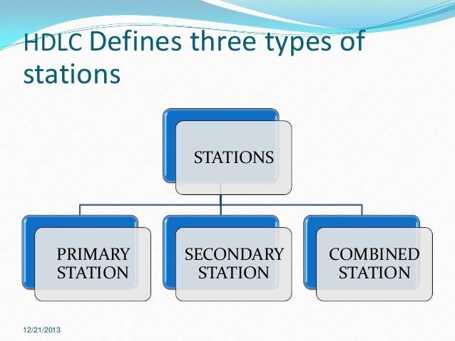
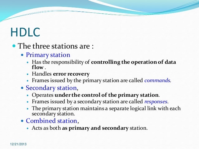
HDLC
An example of what we have seen so far is the
HDLC (High-level Data Link Protocol) commonly known as
X.25. It is a widely used data link protocol, that is bit oriented and uses bit stuffing, like all the other protocols originated in this layer. All bit oriented protocols use a common frame structure shown in the following figure.

You can recognize the frame boarders as they consists of the same bit pattern of 01111110 (flag byte) to indicate the start and the end of the frame. It contains an
address field used to identify one of the terminals on multi-drop lines. The
control field used for sequence numbers, acknowledgement and other purposes. The
datafield that contain arbitrary information and the Check-Sum field.
The Medium Access Sublayer (MAC)
This section deals with broadcast networks and their protocols. The basic idea behind broadcast networks is how to determine who gets to use the channel when many users want to transmit over it. The protocols used to determine who goes next on a multiaccess channel belong to a sublayer of the data link layer called
MAC.
Pure ALOHA
One of the newly discovered algorithms-protocols for allocating a multiple access channel is
ALOHA. The idea is simple. Users transmit whenever they have data to be sent. Frames are destroyed when collision occurs. When a sender detects a collision waits for a random amount of time and retransmits the frame. With this method the best theoretical throughput and channel utilization we can have is 18%. Term throughput means
the amount of work that a computer can do in a given time period
Slotted ALOHA
In slotted ALOHA time is divided into discrete intervals, each corresponding to one frame. A computer is not permitted to send whenever it has data to send. Instead it is required to wait for the next available slot. The best it can be achieved is 37% of slots empty, 37% success and 26% collision.
Nonpersistent CSMA (Carrier Sense Multiple Access)
Before sending, a station senses the channel. If no one else is sending, the station begins doing so itself. However, if the channel is already in use, waits a random time and then repeats the algorithm.
1-Persistent CSMA/CD (Carrier Sense Multiple Access with Collision Detection)
Is an improvement of the previous techniques When a station wants to transmit listens to the cable (
carrier sense). If its busy waits until it goes idle, otherwise it transmits. If two or more stations simultaneously begin transmitting on an idle cable they will collide. As soon as they detect a collision stations abort their transmission (
collision detection). This is very important
enhancement as it saves time and bandwidth. Then stations wait a random time and repeat the whole process al over again. CSMA/CD is widely used on LANs in MAC sublayer such as Ethernet, Token Ring, Token bus etc.
IEEE Standard 802.3 and Ethernet
Ethernet is the most widely-installed Local Area Network technology. Is specified in a standard called IEEE 802.3 (Institute of Electrical and Electric Engineers). An Ethernet LAN typically uses coaxial cable or twisted pair wires. It provides speeds up to 10 Mbps. The devices connected to the LAN compete for access using CSMA/CD protocol. The figure below is an animated gif explaining the basic operation of an Ethernet.
Click on the image to restart it.

Machine 2 wants to send a message to machine 4, but first it 'listens' to the cable to make sure that no one else is using the network.
If it is all clear it starts to transmit its data on to the network (represented by the yellow flashing screens). Each packet of data contains the destination address, the senders address and the data to be transmitted.
The signal moves down the cable and is received by every machine on the network but because it is only addressed to number 4, the other machines
ignore it.
Machine 4 then sends a message back to number 1 acknowledging receipt of the data (represented by the purple flashing screens).
As I stated before, there is a possibility of two machines try to transmit simultaneously over the cable. The result can be observed in the following animated figure.

What happens is that machine 2 and 5 decide to transmit at the same time.
The packets collide and each machine has the ability to detect the collision and immediately abort transmission.
Then they wait for random period of time and transmit again.
IEEE Standard 802.5: Token Ring
The token ring protocol is the second most widely-used protocol on local area networks after Ethernet. The IEEE 802.5 token ring technology provides for data transfer rates of either 4 or 16 Mbps. It is a collection of individual point-to-point links, connecting each terminal, that happen to form a circle. The token ring operation could be seen with the help of the animated figure below.
How it works: A special 3 byte bit pattern called a "token" circulates around the ring. A station wishing the transmit on the ring must seize the token. The station then alters one bit of the token which then becomes the first part of the normal data frame the station wishes to transmit. Only having one token on the ring means that only one station can transmit at a time. This solves the problem of contention and access to the common media.
In the example, machine 1 wants to send some data to machine 4. It captures the token, writes its data and the recipient's address onto the Token (indicated by the yellow flashing screen). The packet of data travels first to machines 2 and 3 that read the address, realize it is not its own, and pass the token to machine 4. This time it is the correct address and so number 4 stores the packet (represented by the yellow flashing screen).
Then machine 4 sends an acknowledgement back to machine 1 to say that it has received the packet (represented by the purple flashing screen).
Machine 5 and 6 forward the acknowledgement to machine 1, who sent the original message.
As soon as Machine 1 receives the acknowledgement, from machine 4 (indicated by the purple flashing screen) regenerates the free Token back on to the ring ready for the next machine to use. |  |